


The forces transmitted by the impact of a vehicle on a retaining wall are determined by assuming a distribution within the wall stem and foundation at a 60° angle, as illustrated in Figure 1.
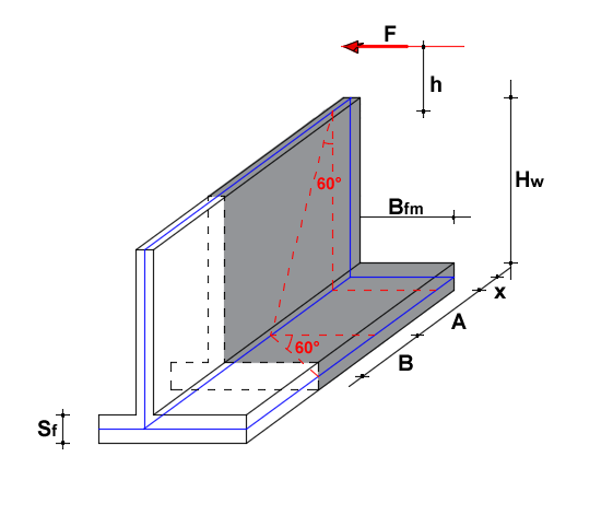
Figure 1- Wall geometry and cross-section dimensions
Design Assumptions The collision is assumed to occur at the end of the wall (the most critical condition). The impact force F is applied over a length x and a height h.
The effective length (L) of the wall that contributes to resisting the impact is calculated as follows (Figure 2):
L = x + (H - Sf/2) * tan 60° + (Bf - Sf/2) * tan 60°
For a 1-meter wide strip of the wall, the design actions are:
-
Fd = F / L(Design Force) -
Md = Fd * h(Design Moment)
In the presence of safety barriers (guardrails), the impact actions on the wall are significantly lower because the barrier absorbs a large portion of the kinetic energy through controlled deformation.

Figura 2- Example of plastic moment calculation for a C-shaped section.
Walls with Guardrail Posts To calculate the shear force at the top of the wall, it is assumed that plasticization occurs at the base section of the post (Figure 3):
Fpl=Mpl/hmontante
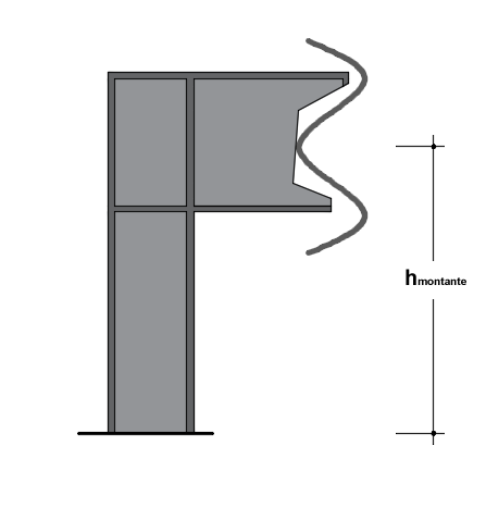
Figura 3 – Structural schematization of the guardrail post and impact height.
In this case, the effective collaborating length is:
L = i * (n - 1) + (H - Sf/2) * tan 60° + (Bf - Sf/2) * tan 60°
Where:
i = spacing between posts;
n = number of posts involved in the impact
The loads at the top of the wall, per linear meter, will be:
-
N = P (Self-weight of the wall and barrier)
-
M = (F / L) * h (Bending moment from impact)
-
T = F / L (Shearing force from impact)