


Application that allows analyzing the time rate of settlement in fine-grained soils in the presence of vertical drains.
Possibility to save and load the project, create a graph of settlement and consolidation trends over time, and export a complete calculation report with theoretical notes in *.docx format.
In the case of fine and very fine-grained soils, the application of a load on the soil involves the onset of an initial constant-volume deformation of the solid skeleton-water complex, which is identified as immediate or undrained settlement, and a gradual deformation over time, connected with the dissipation of excess pore pressures induced by the load application (consolidation settlement).
To predict the settlement trend over time, the consolidation theory (Terzaghi, 1923) is used, with which, knowing the total settlement δtot, it is possible to determine the settlement value at time t δ(t) through the relationship:
![]()
The average degree of consolidation Um is a function of the time factor Tv. The latter assumes the following expression:

function of time t, the coefficient of consolidation cv, and the maximum drainage path H, which in turn is a function of the boundary conditions.

Fig. 1
In fact, if the layer undergoing the consolidation process has a single draining boundary, the maximum drainage path H coincides with the entire thickness of the layer (Figure 1)

Fig. 2
| Uv (%) | Tv |
| 0 | 0 |
| 5 | 0.0017 |
| 10 | 0.0077 |
| 15 | 0.0177 |
| 20 | 0.0314 |
| 25 | 0.0491 |
| 30 | 0.0707 |
| 35 | 0.0962 |
| 40 | 0.126 |
| 45 | 0.159 |
| 50 | 0.196 |
| 55 | 0.238 |
| 60 | 0.286 |
| 65 | 0.342 |
| 70 | 0.403 |
| 75 | 0.477 |
| 80 | 0.567 |
| 85 | 0.684 |
| 90 | 0.848 |
| 95 | 1.129 |
| 100 | ∞ |
Table 1
If, on the other hand, the draining layer has two draining boundaries, both at the top and at the bottom of the consolidating layer, then the maximum drainage path H is equal to half the thickness of the layer (Figure 2).
Correlations between the two quantities Um and Tv, expressed through relationships (Sivaram and Swamee, 1977), can be of great utility:

When consolidation times are excessively long, the consolidation process can be accelerated by installing vertical drains.
Very often these drains are associated with the preloading technique (Figure 3).

Fig. 3
The combination of these two techniques is particularly suitable for all fine and very fine-grained soils such as soft inorganic clays, compressible silts, organic clays, and peats, materials that, under loads due to the embankment body, can lead to excessive settlements and not provide the necessary safety margins.
The installation of drains is generally preceded by the preparation, on the footprint of the embankment body, of a drainage blanket, with the dual function of a working platform and the collection and disposal of the water transmitted by the drains. Regarding the types of drains and their installation methods, historically, sand drains have been more widespread due to their modest construction cost.
However, their construction, using a closed-end mandrel, involved a considerable degree of disturbance for the surrounding soil, with significant remolding of the layer in contact with the drain and consequently the loss of the corresponding advantages. An attempt was made to overcome this drawback through an appropriate installation technique, hydraulic installation. Drains made with this technique are called jetting drains; they have a diameter of the order of 20-30 cm and are installed with a spacing of the order of 2.0-5.0 m.
Generally, it is standard practice to use prefabricated drains, consisting of a central plastic core, the resistant element of the drain, inside which the drainage conduits are created, and an external filter, made either with treated paper or non-woven fabric, with the function of preventing the drain from being clogged by soil particles. They can be considered to have an equivalent diameter of the order of 60-150 mm, and are statically installed at a spacing of the order of i = 1.2 – 4.0 m. Their driving is carried out using equipment that allows reaching depths of the order of 50 m. Also for this type of drain, the installation methods are such as to cause a certain disturbance (“smear” effect), albeit of a much more limited extent compared to previous techniques.
The installation of drains is followed by the installation of appropriate instrumentation, made with piezometers, surface and deep settlement gauges, and possible vertical and horizontal inclinometers, necessary to monitor the evolution of the consolidation process as well as the correctness of the assumptions made during the design phase (Figure 3).
The use of such drains occurs through their staggered installation (parallel rows offset by half a spacing), and therefore it is legitimate to reduce the problem under examination to an axisymmetric problem (Figure 4).
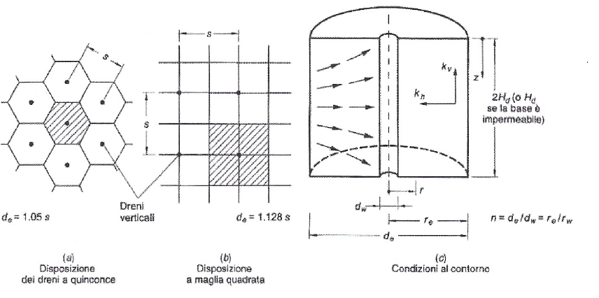
Fig. 4
The theoretical model for calculating consolidation using vertical drains introduces the hypothesis that vertical flow is negligible compared to radial flow and that deformations occur only in the vertical direction.
The resolution of the consolidation equation (Barron, 1948) allows deriving that, in the presence of drains, the average degree of consolidation (Uh) can be evaluated through an expression as a function of:

With:
 Dimensionless time factor;
-
ch = coefficient of consolidation for horizontal flow only = kh / mv γw;
-
kh = coefficient of permeability in the horizontal direction;
-
mv = one-dimensional compressibility coefficient;
-
γw = unit weight of water;
-
de = equivalent diameter of the draining soil cylinder (equal to 1.05 times the drain spacing i if they are arranged in a staggered pattern and equal to 1.13 times i in the case of a square grid layout);
-

- n = ratio between the diameter de of the soil cylinder and the diameter dw of the drain.
The value of dw which, in the case of sand piles is approximately the drilling diameter, for prefabricated strip drains is evaluated as a function of its thickness (b) and width (a), through the expression dw = 2(a+b)/π. The previously expressed solution refers to the ideal case, where the drain can be installed without causing any remolding of the soil and without resistance to fluid flow within it.
To account for remolding (“smear” effect) (Hansbo, 1979, 1981) suggested introducing a correction as a function of:

With:
-
s = ratio between the diameter of the disturbed zone ds and the drain diameter dw;
-
n = ratio between the diameter de of the soil cylinder and the diameter dw of the drain;
-
kh = coefficient of permeability in the horizontal direction;
-
kR = reduced permeability coefficient of the zone adjacent to the drain due to disturbance
The influence of hydraulic resistance, which develops inside the drains (essentially of the prefabricated type), can be taken into account through an expression as a function of:

With:
-
qw = hydraulic capacity of the drain = kw Aw;
-
Aw = area of the drain;
-
l = characteristic length of the drain (equal to the entire length of the drain if it borders a single draining layer, or equal to half the length if the drain borders two draining layers);
-
z = generic depth.
Since the proposed expression depends on depth (F is indeed a function of z), in order to evaluate the average degree of consolidation, it is necessary to take into account an average value of hydraulic resistance evaluated at various depths z along the characteristic length of the drain. It is recalled that the specific discharge of most prefabricated drains varies from 100 to 500 m³/year, therefore the problem in question arises only for long drains and in the presence of high confining stresses (Holtz et al., 1991).
In the case of a compressible layer in which the thickness h is affected by drains only for a thickness h1, the average degree of consolidation (Um) is evaluated through the hypothesis that consolidation develops only radially in the section affected by drains (h1), (to be evaluated via Uh), and only vertically in the section (h2), (to be evaluated via Um of Terzaghi’s Theory), thus superimposing the effects considering the settlements δ1 and δ2 of the respective layers.
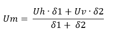
where δ1 and δ2 are the settlements of the layer affected by the drains (h1) and the remaining portion of the compressible layer not affected by the drains (h2), respectively.