


The application allows calculating the bending stiffness per linear meter of various structures such as: piles, micropiles, anchors, and jet-grouting columns. In the analysis, the cylindrical strength of the material (concrete or grout) and its relative elastic modulus are calculated with the following relationships:

Pile walls
By comparing the diameter “D” and the pile spacing “i”, the following two cases can be distinguished:
- If i ≥ D the piles are not secant and we assume


Figure 1 – Piles schematic
2. If i < D, the piles are secant as shown in the schematic reported in Figure 2.

Figure 2 – Secant piles schematic
In this latter case we set:

where:
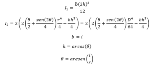
With r equal to the pile radius.
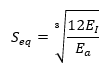
From the inertia, calculated as specified above, the equivalent thickness and stiffness are obtained:

Where:
Ecls = Concrete elastic modulus equal to
![]()
Micropile walls
In the case of micropile walls, in addition to the drilling diameter and the spacing, it is necessary to specify the diameter and thickness of the reinforcement pipe used (Figure 3):
 Figure 3 – Micropile walls schematic
For the calculation of the overall stiffness of the structure, the considerations made for the piles apply. If the spacing value is greater than or equal to the micropile drilling diameter “Dm”:
![]()
The following relationships will be applied:

In the event that i < Dm, we will have:
![]()
Where:
Da = outer diameter of the tubular pipe;
s = thickness of the tubular pipe
In the overall stiffness formula, the inertia values of the tubular pipe are subtracted to avoid them being counted twice:
![]()
Where:
Em = grout elastic modulus equal to 5700 √Rck
Ea = steel pipe elastic modulus
In calculating the equivalent thickness, it is possible to choose to homogenize with respect to the steel or the injection grout.
- Homogenization with respect to the grout:

- Homogenization with respect to the steel:
Micropiles or Jetting arranged on two alignments
A problem similar to the micropiles case but with an additional variable, the spacing between the alignments (dfile) (Figure 4):

Figure 4 – Schematic of micropile walls in two alignments
The problem in this case is solved by estimating an average stiffness value (EImed), calculated from two extreme values by making the following assumptions:
- Absence of interaction between the rows:
![]()
- Perfect connection between the two alignments (plane sections hypothesis):
![]()
Where:
Ai = Area of a single alignment or row;
Ii = Inertia of a single alignment or row.
The average stiffness depends on the stiffness of the individual elements, the degree of connection between them, the distance between the alignments, and the deformability of the soil. The average stiffness value just calculated, being derived from an arithmetic mean, is approximate and must be verified with more complex methods.
The application outputs all three values (minimum, maximum, and average) for both stiffness and equivalent thickness.
Diaphragm walls
In the case of diaphragm walls, the stiffness is simply calculated with the relationship:


Figure 5 – Diaphragms schematic
Anchors
In the case of anchors, the axial stiffness is derived from the following expression:
![]()
Where:
A = Total area of the reinforcement
Leq = Equivalent (deformable) length equal to Llib + Lbulbo/2 where Llib is the free length and Lbulbo is the bulb length
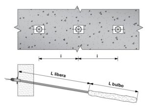
Figure 6 – Anchor schematic